 [1]
[1]  [2]
[2]  [3]
[3] The Ray Trace Language (RTL) has been developed over a period of about 25 years. It is a geometric ray trace language based on very simple primitive functions of reflection or refraction at plane surfaces. It was originally written in APL (A Programming Language) and used on an IBM 360 computer to provide information for developing an interactive simulation of the Fine Error Sensor (FES) used on the International Ultraviolet Explorer (IUE) satellite, a spectrographic astronomical observatory instrument launched in 1978 and still operational as of 1996.
From very simple beginnings the program was expanded in order to meet the needs of developing satellite instruments that became more and more complex. In the IUE project, RTL grew from modeling the Fine Error Sensor as a thin lens approximation to analyzing the dispersion scaling of the echelle spectrograph formats on the flight cameras - eventually modeling the Ritchey-Chretien 45cm diameter telescope as well. The RTL language has migrated from APL on the IBM mainframe to APL on PC computers, making a detour to the Apple II where it was implemented in the FORTH language.
At Evans Engineering it has been developed as a proprietary ray trace code used for developing complex 3 dimensional optical models that interface with 3D AutoCAD drawings. Once mechanical configurations are defined, RTL is used to convert to ACCOS, SYNOPSYS, or Code-V models for surface optimization. Some of surface optimization and tolerance analysis can be done directly in RTL, but it is a slower process than using those specialized codes. When new problems are confronted, it is usually quickest to resolve the problems using RTL before converting to one of the commercial codes.
RTL uses a generalized vector matrix description of rays and surfaces which makes it easy to translate between optical models and 3D mechanical drawings (AutoCAD 12 & 13 or other modelers via .DXF and IGES translations).
In addition to handling plane surfaces it currently can analyze spheres, ellipsoids, paraboloids, hyperboloids, cylinders, polynomialoids, diffraction gratings in reflection and transmission, and surfaces described by Zernike polynomials. It also has the capability of doing polarization analysis of optical systems configured from these surfaces. The precision and accuracy of RTL has been confirmed on numerous occasions by detailed comparison with GOALS, ACCOS, SYNOPSYS, and Code-V optical models.
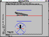
[1] RTL screen image of ray trace of an unfolded version of a infrared reimaging filter camera. The field-of-view is 10 arc minutes square. The detector is 256 pixels square. The design is based on two paraboloids, one each for collimating and reimaging. The system is diffraction limited.
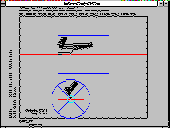
[2] RTL screen image of the same optical design folded to fit within the allowed instrument volume.
[3] RTL sample screen displays of menu "FMENU" call and selected listings of the RTL main program for this spectrograph design.