IRAC Channel 4 Ghost Analysis with ASAP
Dennis Evans, Evans Engineering 301-262-2230
http://www.evansopticalengineering.com
dennis@evansopticalengineering.com
Analysis done 2/4 - 2/7/00
The IRAC Channel-4 Throughput Calibration System was modeled in ASAP (Advanced Systems Analysis Program, Breault Research Organization). The Output of the 3-inch diameter integrating sphere was modeled as a perfect Lambertian disk, with a radius of 14 mm. The Disk was modeled first because it was likely that the full model of the integrating sphere would take a long time to run and because a test case was needed anyway to separate the performance of the integrating sphere system.
Because of the limits of disk space, only about 850 MBy of storage is available for dynamically saving the raytrace file needed for analysis. About 2.5 million source rays will generate a file that large.
ASAP controls operating efficiency by allowing the source rays to illuminate only a preselected cone angle. For the IRAC, a 21 degree cone half angle allows full illumination of the shutter mirror.
Someone suggested that the disk be made smaller so the edges and alignment coud be seen. This analysis is a result of the model with the disk reduced to 1/4 its radius, i. e. 14/4 mm. The ASAP model still uses 500-thousand rays from the source. This increases the flux density in the model a factor of 16 and improves the digital noise on the random ray model.
Ghost Fraction = (0.242379E-02 - 0.240756E-02)/ 0.240756E-02 = 0.00674127 (=1/148.34)
The coating applied to the transmission surfaces was 0.05 reflection, 0.95 transmission. A single reflection would reduce the flux to 1/20th; a double reflection would reduce the flux to 1/400th of the transmitted flux.
In order to get to the detector, there must be an even number of splits. Setting Split=4 would be needed to analyze ghosts that would be reduced by (1/20)**4 = 0.00000625 (6.25E-6) which is negligible for diffuse reimaging ghosts.
There are 4 ghost images that can be seen in the spot plot images.
There are two in-focus ghost images that should correspond to ghosts off the Beam Splitter and the Filter. The characteristics are "in-focus" and shifted about 90-degrees with respect to each other. They should be equal in intensity according to the Coating model
There is a close-in diffuse ghost.
There is a broader diffuse ghost.
These last two ghosts should be formed by multiple reflection off the lens surfaces.
Each ghost encountered should have about 1/400th of the main transmitted flux. The ghosts from the Beam Splitter and the Filter should have a total of 1/200th. An additional 1/400th ghost would make the total 1/133 that is more than the ghost flux present. The general impression is that the close-in ghost would contain nearly all that energy and that the diffuse ghost would contribute very little flux.
The ghosts from the Beam Splitter and Filter should be uniform over most of the field. The other ghosts may be the ones causing the images which are seen in the test sequence images.
It will take another day or two to isolate the ghosts and subtract the direct image from the full size diffuser model.
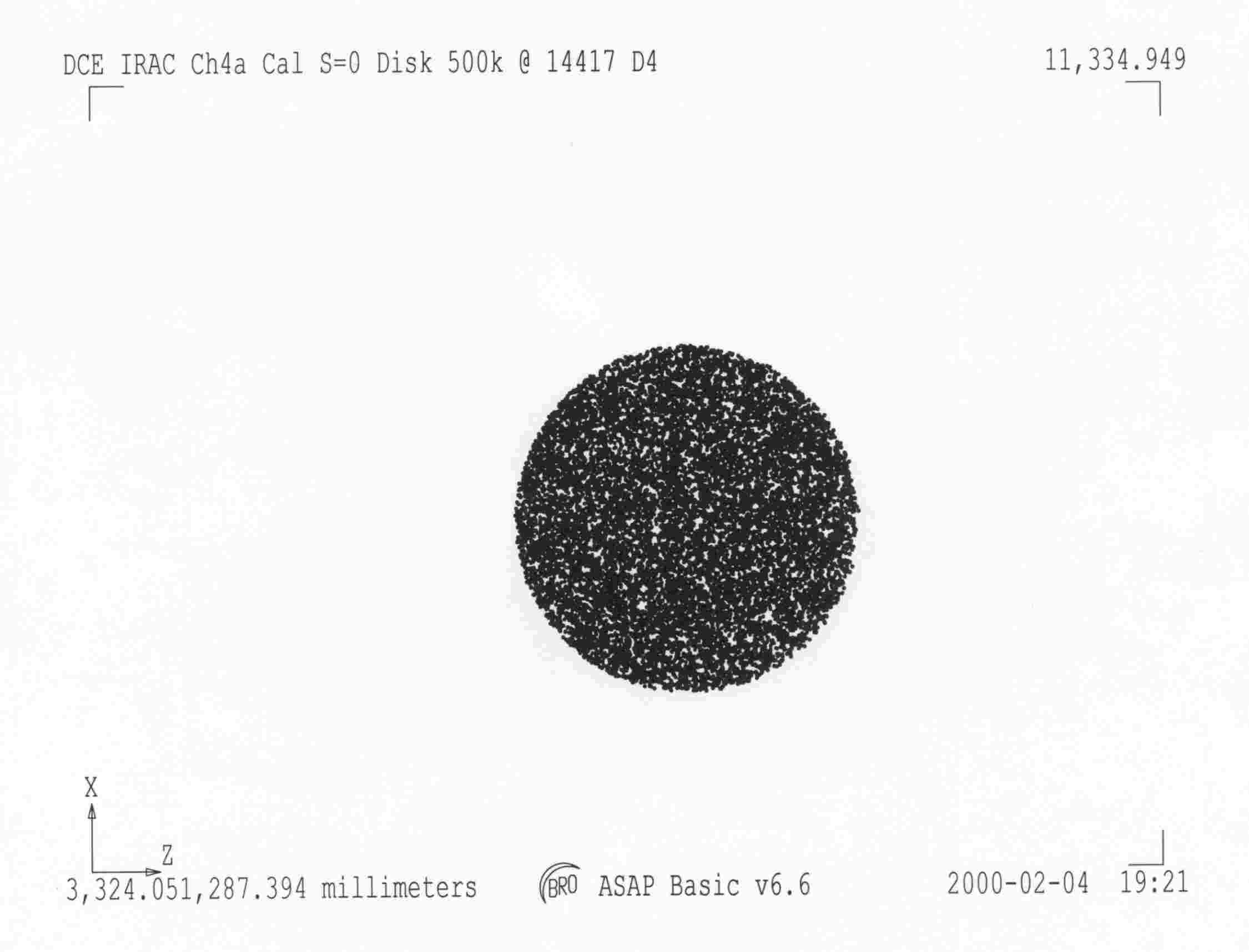
Figure 1: Spot plot of 14417 rays which get to the detector when there is no ray splitting allowed at the optical surfaces
Figure 2: A logarithmic display of the spot data clipped to include only the 100 to 80% levels
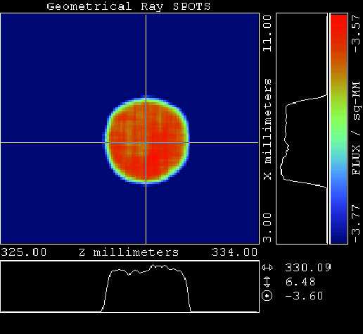
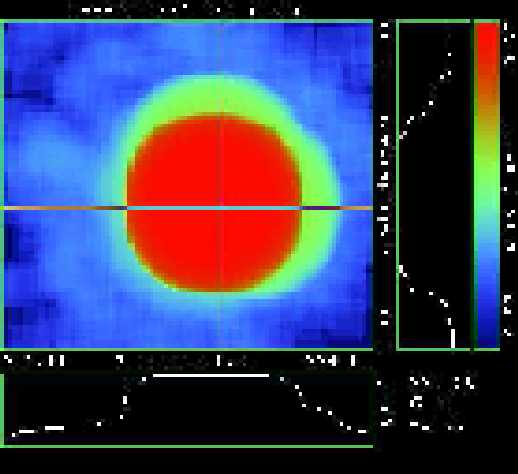
Figure 3: A logarithmic display of the spot data clipped to include only the top 1.5 orders-of-magnitude.
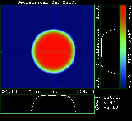
Figure 4: The spot plot for the ray trace with the split level set to 2. This allows a ghost that needs 2 reflections to form. This is the minimum number that is needed to form a ghost in the direction of the transmitted light.
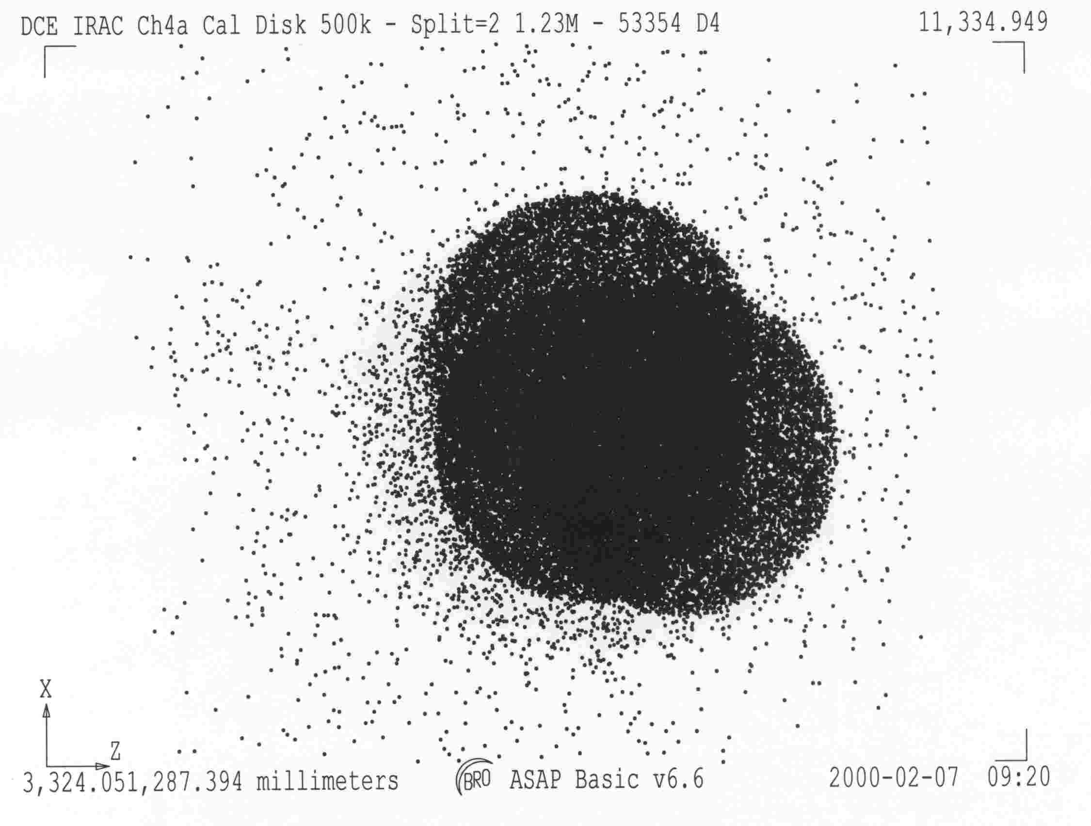
There are 4 ghost images that can be seen in the spot plot images.
There are two in-focus ghost images that should correspond to ghosts off the Beam Splitter and the Filter. The characteristics are "in-focus" and shifted about 90-degrees with respect to each other. They should be equal in intensity according to the Coating model
There is a close-in diffuse ghost.
There is a broader diffuse ghost.
Ghost Fraction = (0.242379E-02 - 0.240756E-02)/ 0.240756E-02 = 0.00674127 (=1/148.34)
Although there are 53354 rays in this image instead of the 14417 in the first image, the 14417 for part of the set and carry 99.33% of the flux.
Figure 5: The Ghost Image restricted to the top 0.2 (log) of the flux. (virtually identical to Figure 2)
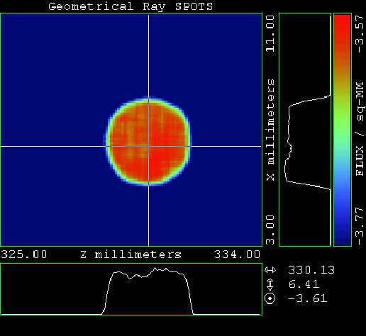
Figure 6: The Ghost Image restricted to the top 1.5 (log) of the flux. (virtually identical to Figure 3)
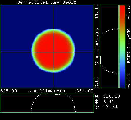
Figure 7: The Ghost Image restricted to the top 4.0 (log) of the flux. The Beam Splitter and Filter ghosts are visible.
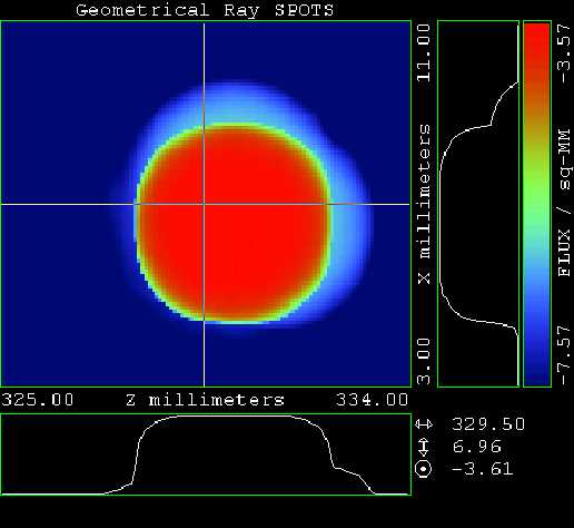
Figure 8: The top 6 orders of magnitude displayed on a log scale. The outer diffuse ghosts are visible.