 [A]
[A]  [B]
[B]AGeoS Imager - 2D and 3D Optical Layouts
Stray Light Baffles and RTL Ray Trace Rays
Three Mirror, Afocal Telescope
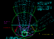
[A] 2D Layout of stray light baffles with telescope axis aligned parallel with launch thrust axis and earth's spin axis. This results in a scan mirror sitting on a three position turntable viewing a choice of the black body, the earth, or the perforated plate by approximately 60 degree general rotation steps. In each stepped angular position the scan mirror needs to be able to do precision scanning over a 10 to 20 degree angular range. This layout allows an internal baffle to be attached to the turntable which will block completely the stray light to the two fields not being viewed.
[B] 2D Layout of stray light baffles with telescope axis, center of scan mirror, and center of perforated plate perpendicular to the launch thrust vector in a plane parallel to the equator of the earth. This layout uses the minimum length of the vehicle shroud, but the complicated paths to the earth, black body, and perforated plate do not allow room for a baffle in the vicinity of the scan mirror. The black body plate is above or below the equatorial plane. This makes the 3 position control more complicated than in layout [A].
In both configurations, the doors that protect the scan mirror during launch open once and become part of the stray light baffle system. The door in front of the perforated plate opens when the plate needs to be used. In configuration [A] with the internal baffles on the scan mirror, the door does not need to be closed between perforated plate calibration sessions for stray light control. It may need to be closed for thermal control or contamination control.
Two-Mirror, Confocal Paraboloids, Afocal Telescope
A two mirror, confocal paraboloid, afocal telescope has been suggested as a potential telescope for a more compact version of an AGeoS Imager instrument. One of the driving forces for considering this design is to produce a "smallest version" of the Imager instrument. In order to use a two-mirror, Gregorian-like, afocal telescope, a smaller field-of-view is required in order to achieve the image quality specification. A first attempt at a telescope design by Mark Wilson showed that a two-mirror system was nearly diffraction limited over an 0.6 degree circular diameter field-of-view. A square field-of view of 0.8 degrees is needed for the Imager instrument. Consideration of scan rates (1-degree per second) and this smaller field-of view are compatible with the full earth scan every 15-minutes, with a local storm scan every 1-minute. There is a potential of being able to increase the scan rate to 2-degrees per second, but this may not be an absolute requirement. To study the potential for smaller packaging, I arbitrarily increased the two-mirror intervertex distance from 700 mm to 1000 mm. This will improve the image quality without increasing the overall size of the package.
One outstanding stray light suppression feature of this design is that direct sunlight need never strike the secondary mirror under any normal observing conditions.
[C] A layout based on the concept considered by the IMDC study. The overall size was chosen to keep the flat layout of the detector bands on the optical bench. The overall size is determined by the radiator area for the cold optical bench. In this particular layout the cold bench and therefore the radiator surface are at the bottom of the side (lower right) view.
[D] A smaller package can be achieved by offsetting the main optical path with two fold mirrors and folding the detector bands by adding a fold mirror between the front and back lenses of each reimaging optics set for each band. Six extra fold mirrors are required for this configuration. The overall configuration is roughly the same size as the GOES imager, considering the volume needed for the GOES Imager sun shade and radiator cooler.
[E] An even smaller package achieved by locating the detector bands along the telescope axis. The beamsplitter configuration is more complex, but only marginally so. The detector bands have no internal fold mirrors and it looks like no fold mirrors are needed to offset the main path to the detectors. This package would physically fit on the same shelf that the GOES Imager is mounted on GOES-8 and -9. The detector bands would still be modular. It looks to me like [E] would be distinctly preferred to the [D] configuration, being smaller and having fewer fold mirrors.
3D AutoCAD Drawing - RTL version of [E] above
Drawing AGeoS-Two-02-3D (AutoCAD 13)
3D rays are included from an RTL ray trace. In this set, only the central ray is shown. All rays defining the 0.8-degree field-of-view and 300 mm diameter pupil stop are included in the full drawing.
[V1] View 1: Front view looking into the telescope primary mirror.
[V2] View 2: Side view. Radiator & Optical Bench at top.
[V3] View 3: Top view.
[NT] Notes