 Figure 1: Labeled
ZEMAX L3d display
Figure 1: Labeled
ZEMAX L3d displayASAP Alignment Models for 28 & 39 mm Apertures
Dennis Charles Evans
Evans Engineering
February 18-23, 2000
ASAP Analysis of Flight Channel 4 IRAC Optics at 8 microns
Shutter Mirrors Used
DCE – Top: Derived by Dennis Charles Evans to center Calibrator Aperture on Lens Axis
DCE IDM Top: The Top Shutter Mirror Facet derived from the IDM IGES model
CTM-1 A verbal reference surface normal only, no position, from Cathy Trout Marx.
CTM24A The first reference from Cathy Trout Marx in the e-mail of 2/16/00
CTM24B The second reference from the 2/16/00 e-mail. (0.040 shift)DCE IDM Top: The Top Shutter Mirror Facet derived from the IDM IGES model
Images were created for this mirror with the 28-mm and 39-mm aperture.
The mirror was rotated about the motor shaft by 0.5, 1, 2, and 5 degrees
to see if the images generated matched the December 1999 test images.
Multiple "Fast" Builders:
There are too many optical elements to fit in one ASAP builder spreadsheet. Also, all the test elements used to develop the model take up a lot of time during ray tracing even when they are "Clear". Eliminating the extra elements and cutting the rays in the Calibration Source for 2-million to 500,000 improved the raytrace run time from 4.16-hours to 3-minutes.
Sources = IRAC-Ch4a-Cal-Fast-Sources.ent
[Wavelength 8.015980: Coatings Mirror Black Zero Clear Arf05;
CylBack, A & B linear sources, A & B tip point sources, & Detector 4 ID Sources]
Cylinder = IRAC-Ch4a-Cal-Fast-Cylinder.ent [Cylindrical approximation of Calibrator with Baffles A & B]
Baffles A (upper) and B (lower) are in the correct 3-D location. The Cylinder just encloses the volume of the calibrator sphere, giving a Lambertian illumination through the apertures so the positions of the baffle images will be correctly located in the image plane.
39mm Aperture = IRAC-Ch4a-Cal-Fast-Aper39mm.ent
28mm Aperture = IRAC-Ch4a-Cal-Fast-Aper28mm.ent
The 28-mm and 39-mm apertures are correctly located in 3-D space.
Shutter
IRAC-Ch4a-Cal-Fast-Shutter-CTM1-Top.ent
IRAC-Ch4a-Cal-Fast-Shutter-CTM24A.ent
IRAC-Ch4a-Cal-Fast-Shutter-CTM24B.ent
IRAC-Ch4a-Cal-Fast-Shutter-DCE-Top.ent
IRAC-Ch4a-Cal-Fast-Shutter-DCE-Top-IDM.ent
IRAC-Ch4a-Cal-Fast-Shutter-DCE-Top-IDM-rot-1.ent
IRAC-Ch4a-Cal-Fast-Shutter-DCE-Top-IDM-rot-2.ent
IRAC-Ch4a-Cal-Fast-Shutter-DCE-Top-IDM-rot-5.ent
IRAC-Ch4a-Cal-Fast-Shutter-DCE-Top-IDM-rot-half.ent
Optics = IRAC-Ch4a-Cal-Optics.ent
A typical ASAP run consists of running: the Fast Sources; The Cylinder; one of the Apertures; one of the Shutters, and the Optics. The build is then plotted, raytraced, spot plotted, and pictured (color image).
Summary:
For all 5 Shutters, Detector 4 is fully illuminated with the 39-mm aperture. Channel 2 comes the closest at one corner.
The images of Baffles A & B interior to the Calibration Sphere will not be imaged on the detectors with the Aperture opened from 28 to 39-mm.
The model does not include the details of the baffles in the tunnel from the Calibrator to the shutter mirror. Those baffles are narrowest in vertical width. The mirror shifting is almost entirely vertical so this should not be a problem. There may be a trace of vignetting at the bottom of the Channel 4 and the top of the Channel 2 test images that may be associated with these baffles, but this should not shift with increasing the Calibration Sphere aperture size.
Since Band 4 is fully illuminated, Band 2 should also be illuminated. This involves only assuming that the Beam Splitter reflects at the design angle. There is evidence from the test images that this reflection is not at the design angle or the detectors are slightly shifted.
By symmetry, Bands 1 & 3 should be OK, but this should not be left entirely to the assumption of symmetry. When Bands 1 and 3 are checked, the Calibration tunnel baffles will be added to the ASAP model.
Figure 1: Labeled
ZEMAX L3d display
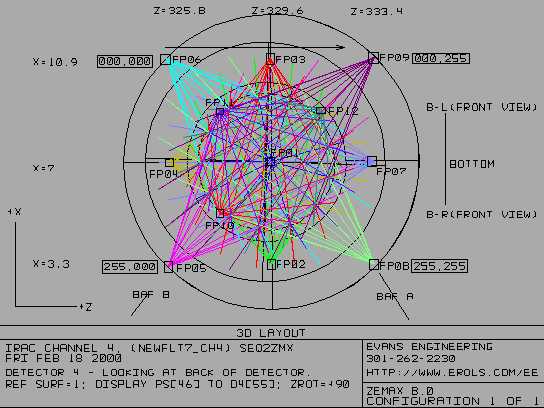
This is a Layout 3d image of the Channel 4 detector generated by ZEMAX. This view was selected to match the default views of Channel 4 generated by ASAP. Be very careful when considering pixel and image alignment. There are mirror inversions between channels in the same sets (1 & 3 and 2 & 4) and it is unlikely that all the images available are displayed in the same 000,000 to 255,255 orientation. I had to add the ID sources behind the Detector and carefully measure the dimensions in 3D space to get the orientations to be consistent. The labeling on this image represents the third careful attempt (the first two seemed right, but were inconsistent with the rest of the images.
This is the equivalent of a view through the back of the Detector. The incoming light is moving out of the computer screen toward you.
These are the images that were used for comparison in this analysis
 <Ch1
<Ch1 <Ch2
<Ch2  <Ch3
<Ch3  <Ch4
<Ch4
Based on a discussion with Cathy Trout Marx on
2/22/00, all these images are oriented so the top of the detector
is to the left,
and the image is displayed as it would appear facing the
detector.
Channels 3 & 4 are the ones that go through
the beamsplitters.
Channels 1 and 2 are reflected off the beamsplitters and are
mirror images of 2 & 4.
The beamsplitter mirror-axis is horizontal in all the displays in
this report.
Aperture Model Alignment Results
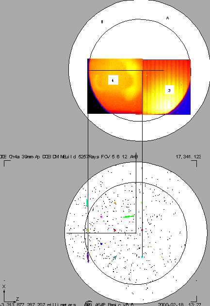 Figure 2: Channel 3
& 4 Alignment
Figure 2: Channel 3
& 4 Alignment
All the ASAP analysis for this report was done on Channel 4. All the other Channels are located by aligning with the 28-mm diameter aperture outline.
The upper white circles are copies of the circles generated on the ASAP 39-mm aperture spot display immediately below.
The detector display width is 256 x 0.30 = 7.68 mm.
The distance between the top two field points (6 & 9) is 7.73 mm.
The Spot Plot is scaled so the 6 to 9 field point distance is 7.73 mm based on the width of image 4 being 7.68 mm. The best fit outer diameter to the 39-mm aperture was visually centered on the Spot Plot. The 28-mm aperture diameter was scaled from the 39-mm circle. The circles were copied and shifted above to provide an alignment reference for the December 1999 Channel 4 and then 3 images.
The ID relationships between the upper and lower sets are as if the lower ASAP set were to be folded about a horizontal line midway between the two sets and positioned on top of the December 1999 images. Refer back to Figure 1 and note that the A & B baffles inside the Calibration Sphere are imaged near the A and B on the top image. The Vignetting from the B baffle can be seen to the bottom left of the spot plot.
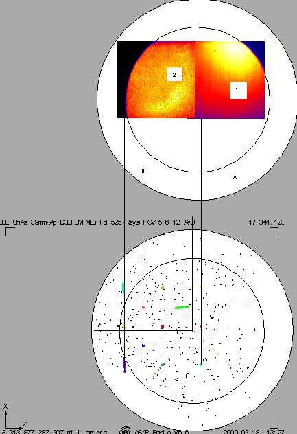 Figure 3: Channel 1
& 2 Alignment
Figure 3: Channel 1
& 2 Alignment
The white circles and ASAP spot plots in Figure 3 are identical copies of the same features in Figure 2.
The images for Channel 1 & 2 are mirrored by the Beamsplitter so that the upper images match the ASAP spot plot orientation in the lower part of the figure.
The vignetting by the B baffle is correct for Channels 4 and 2. There is a parallax shift so the vignetting for Channels 1 and 3 should be shifted to the right where the A is located in the upper set.
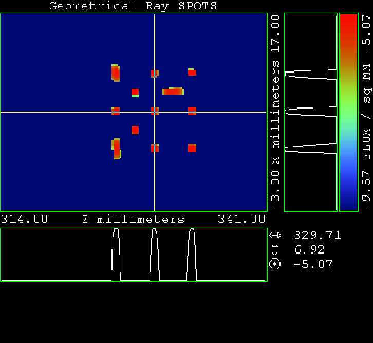 Figure 4: Channel 4
Detector Fiducials
Figure 4: Channel 4
Detector Fiducials
The fiducials are small light sources that were placed a few microns behind Detector 4 in the ASAP model. Fiducials 5, 6, and 12 are elongated so that the pattern is unambiguously asymmetric. Refer back to Figure 1 to see the Field Point Identification Numbers.
These fiducials always occur in the same place in all of the color images and spot plots.
 Figure
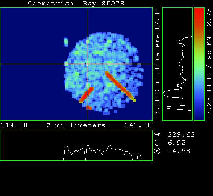
5: Channel 4, DCE IDM Mirror, 28-mm Aperture with 1/2-degree Open
Shaft Rotation
Figure
5: Channel 4, DCE IDM Mirror, 28-mm Aperture with 1/2-degree Open
Shaft Rotation
The aperture image is moved down from the design location as the Shutter Mirror Shaft is rotated so that it is "opening" from the design closed position.
The left red diagonal is the image of a source that runs along the diagonal from the center of the calibrator aperture toward the B baffle. The inner radius of the diagonal is 7-mm and the outer radius is 14-mm. The red dot in the lower left is an image of a source that is on the center of the tip of the B baffle. There is a corresponding source on the A baffle, but it is not visible in this view.
The right red diagonal is the image of a source that is along the diagonal from the center of the aperture toward the A (upper) baffle in the Calibration Sphere. The inner point is at the center of the aperture and the outer limit is at 14-mm radius.
The shift to the right is from parallax between the center of the Calibration Sphere and the center of the 28-mm Aperture.
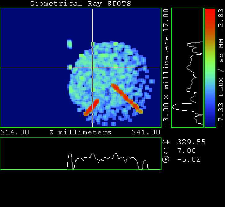 Figure
6: Channel 4, DCE IDM Mirror, 28-mm Aperture with 1-degree Open
Shaft Rotation
Figure
6: Channel 4, DCE IDM Mirror, 28-mm Aperture with 1-degree Open
Shaft Rotation
This is approximately the same as the Channel 4 image from the December 1999 test images shown above, noting that image should be mirrored about a horizontal line to be displayed in the same orientation as the December 1999 image.
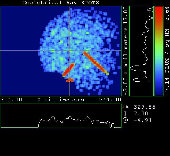 Figure 7: Channel
4, DCE IDM Mirror, 39-mm Aperture with 0-degree Open Shaft
Rotation, i.e. the design reference position.
Figure 7: Channel
4, DCE IDM Mirror, 39-mm Aperture with 0-degree Open Shaft
Rotation, i.e. the design reference position.
The vignetting by a zero reflectance B-Baffle is seen at the lower left, along with the red image of the light source on the tip of the B-Baffle.
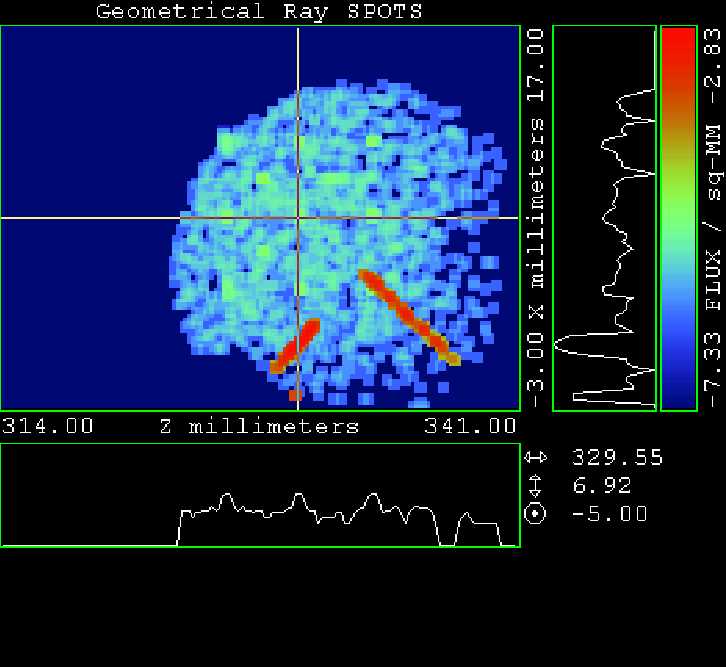 Figure 8: Channel
4, DCE IDM Mirror, 39-mm Aperture with 1-degree Open Shaft
Rotation, i.e. the shaft is rotating to open the Shutter Mirror
from the design reference position.
Figure 8: Channel
4, DCE IDM Mirror, 39-mm Aperture with 1-degree Open Shaft
Rotation, i.e. the shaft is rotating to open the Shutter Mirror
from the design reference position.
At 1-degree Shutter Mirror Shaft rotation, the image of the 39-mm Aperture is just starting to move off the detector. This can be seen by the fiducial in the upper left of the image.
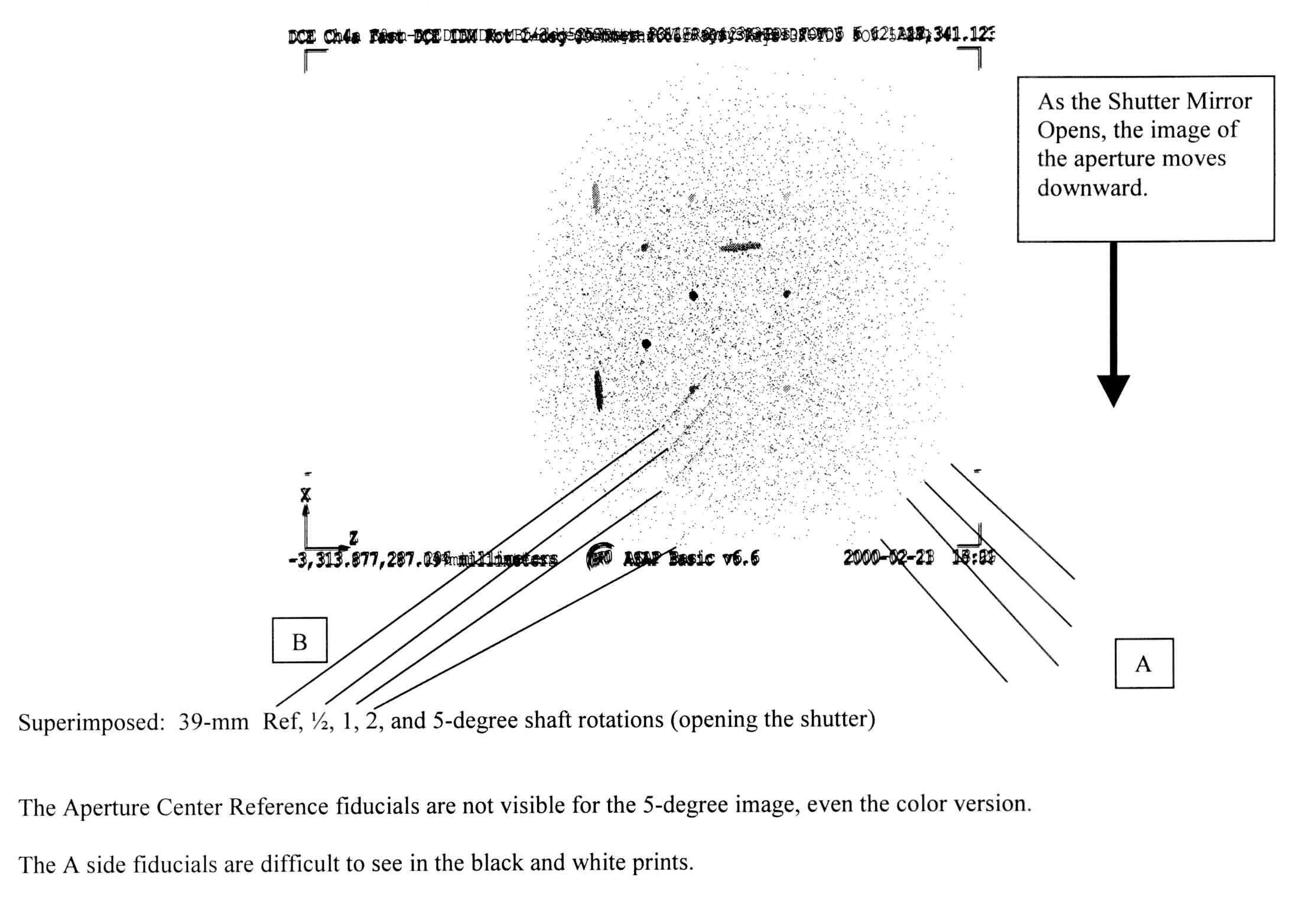 Figure
9: Channel 4, DCE IDM Mirror, 39-mm Aperture with 0, 1/2, 1, 2,
and 5-degree Open Shaft Rotations superimposed.
Figure
9: Channel 4, DCE IDM Mirror, 39-mm Aperture with 0, 1/2, 1, 2,
and 5-degree Open Shaft Rotations superimposed.
The shaft is rotating to open the Shutter Mirror from the design reference position.