Advanced Geosynchronous Studies [AGS]- Weather Imager
Version with 2-axis Scan Mirror and Deployable Calibrators
Version with 3-axis Scan Mirror and Fixed Position Calibrators
AGeoS Imager - 2D and 3D Optical Layouts
 [1] [1] [2] [2]
[Left, 1] A 3D perspective view from a detector inside a small telescope showing numerous internal reflections which interfered with the performance of the device.
[Right, 2] A 3D perspective view looking into a Cassegrainian telescope showing reflections of the light source which was contributing to calibration errors and performance misunderstandings.
 [3] [3] [4] [4]
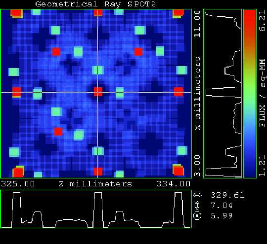
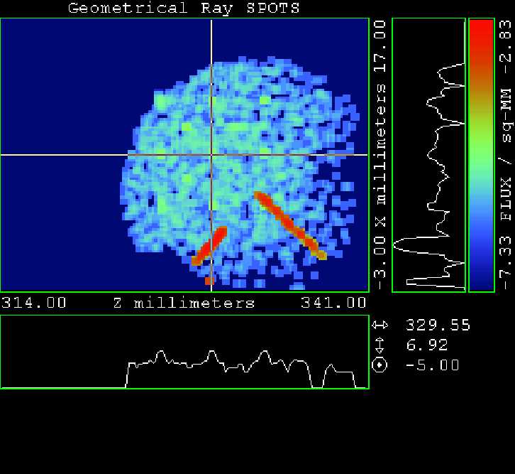
[Left, 3] An RTL ray trace of a 10 arc-minute square field imaged onto a 256 square array infrared detector. The ray path of a dual paraboloid set has been folded in order to fit into a 30 degree sector of a 10 inch long cylinder.
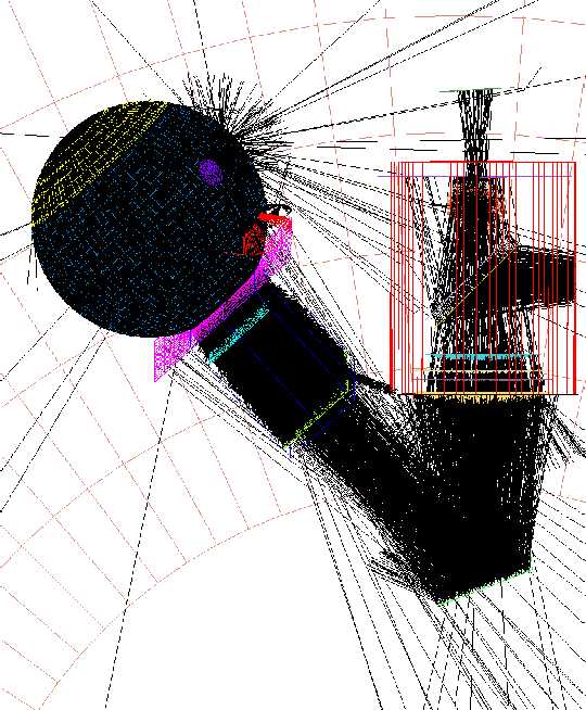
[Right, 4] A perspective view from the entrance lens of a star tracker looking toward the sky. The green object is the back side of a sunshade on the payload instrument which is illuminated by the full earth. With this object visible to the tracker, the tracker could not meet performance specifications. The tracker stray light baffle was moved 1/2 inch and redesigned so the instrument sunshade could no longer be seen from the star tracker lens.
 [5] [5] [6] [6]
[5] A perspective view from the entrance baffle vane of an infrared telescope. Note the convergence of the interior vanes to the right side of the image. When the vane edges were moved away from a uniform cone by a few millimeters, the stray light in the instrument was reduced about 2 orders-of-magnitude. This shows the power of 3D modeling and image rendering connected with APART/PADE and other analytical tools.
[6] A rendered view of the same telescope as in [5], with the primary and secondary mirrors made reflective. The detector can be seen, as desired, but some edges that should not be illuminated can also be seen. Additional baffle vanes inside the throat of the central conical baffle were recommended.
 [7] [7]
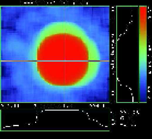
[7] The image quality of the optics in an instrument such as the GOES-8 and -9 (Geostationary Observational Environmental Satellite) has as much influence on performance as the detector aperture size. For this model of GOES, the perfect 26 microradian aperture is represented by a square, 59 units on an edge. The image that best matches the result of having a star drift across the aperture is the one with a normal distribution and a half width of 20 units.
<Link to ISAL/IDL Typical Tasks>
IRAC/SIRTF First Images - December 2003
    
Infrared Array Camera (IRAC) Tasks
IRAC Ghost Images
IRAC Channel 4 Point Source Ghosts
ASAP 28-mm & 39-mm Aperture Model Results
ASAP Integrating Sphere Model Results
|